E9NC-T
Contact-Type Smart Sensor
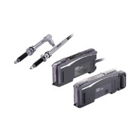
Tough Contact Sensor
Related Contents
- Features
- Lineup
- Specifications
- Dimensions
- Catalog / Manual / CAD / Software
last update: July 1, 2014
Sensor Heads
| Type | Straight type | E9NC-TH5S | E9NC-TH12S | |
|---|---|---|---|---|
| Right-angle air type | E9NC-TH5L | E9NC-TH12L | ||
| Flanged type/Straight type | E9NC-TH5SF | E9NC-TH12SF | ||
| Flanged type/Right-angle air type | E9NC-TH5LF | E9NC-TH12LF | ||
| Measuring range (Moving range) | 5 mm | 12 mm | ||
| Resolution | 0.1 μm | |||
| Precision *1 | 1 μm | |||
| Measuring
force *1 |
Upward | 0.35±0.25 N | 0.4±0.3 N | |
| Horizontal | 0.4±0.25 N | 0.5±0.3 N | ||
| Downward | 0.45±0.25 N | 0.6±0.3 N | ||
| Indicator (Preamplifier) | Operation indicator (blue/red) | |||
| Ambient temperature range | Operating: -10 to 55°C; Storage: -20 to 60°C (with no icing or condensation) | |||
| Ambient humidity range | Operating and storage: 35% to 85% (with no condensation) | |||
| Maximum response speed | 80 m/min | |||
| Origin detection speed | 80 m/min | |||
| Origin position | 1 ±0.5 mm from the spindle push-out position (the lowest point) | |||
| Vibration resistance (destruction) | 100 m/s2 (20 to 2,000 Hz) 20 minutes each in X, Y, and Z directions | |||
| Shock resistance (destruction) | 1,000 m/s2 3 times each in X, Y, and Z directions | |||
| Degree
of pro- tection |
Head | Right-angle air type | IEC IP67 (only when a hose elbow and air hose are connected) | |
| Straight type | --- | |||
| Preamplifier | --- | |||
| Number of sliding operations | 92 million times (based on OMRON’s dedicated evaluation) | |||
| Probe | Carbide with a round surface, screw thread size: M2.5 | |||
| Connecting method | Pre-wired connector (2 m from the Sensor Head to the Preamplifier) | |||
| Materials | Sensor Head | Stainless steel (SUS303) | ||
| Rubber boot | Nitrile rubber (NBR) | |||
| Preamplifier | ABS | |||
| Probe contact point *2 | Carbide | |||
| Cable | PVC | |||
| Hose elbow for air (included)
(Right-angle air type only) |
Nickel-plated brass | |||
| Tightening nut, Wave washer
(Flanged type only) |
Tightening nut: Stainless steel (SUS410), Wave washer: SK5 | |||
| Weight (packed state/Sensor Head only) | Approx. 340 g/approx. 110 g | |||
| Accessories | Common: Wrench, Instruction Manual
Right-angle air type: Hose elbow Flanged type: Tightening nut, wave washer, clamp wrench, pin |
|||
*1. These values were measured at an ambient temperature of 20°C.
*2. For the case of the provided E9NC-TB1 (3-dia. probe)
Amplifier Units
| Type | Communications | ON/OFF output | |
|---|---|---|---|
| NPN output | E9NC-TA0 | E9NC-TA21 | |
| PNP output | E9NC-TA51 | ||
| Connecting method | Connector for Sensor
Communications Unit |
Pre-wired type | |
| Inputs/
outputs |
Outputs | - *1 | 2 outputs |
| External inputs | 1 input | ||
| Power supply voltage | Supplied from the connector through the
Sensor Communications Unit |
10 to 30 VDC, including 10% ripple (p-p) | |
| Display resolution | 0.1 μm min. | ||
| Power consumption *2 | At Power Supply Voltage of 24 VDC
Normal mode: 2,040 mW max. (Current consumption: 85 mA max.) Eco ON: 1,800 mW max. (Current consumption: 75 mA max.) Eco LO: 1,920 mW max. (Current consumption: 80 mA max.) |
||
| Control outputs *3 | - | Load power supply voltage: 30 VDC max.,
open-collector output Load current: 100 mA max. in total for the 2 outputs (Residual voltage At load current of less than 10 mA: 1 V max.,at load current of 10 to 100 mA: 2 V max.) OFF current: 0.1 mA max. |
|
| External inputs | - | Refer to *4. | |
| Indicators | 7-segment displays (white)
GO indicator (orange), HIGH/LOW indicator (orange), NO/NC indicator (orange), PRST indicator (green), ST indicator (blue) |
||
| Protection circuits | Power supply reverse polarity protection
and output shortcircuit protection |
Power supply reverse polarity protection,
output short-circuit protection, and output reverse polarity protection |
|
| Response
time |
Super-high-speed
mode (SHS) |
Operate or reset: 3 ms | |
| High-speed
mode (HS) |
Operate or reset: 10 ms | ||
| Standard mode
(Stnd) |
Operate or reset: 100 ms | ||
| Giga mode
(GIGA) |
Operate or reset: 1,000 ms | ||
| Threshold setting | Smart Tuning (2-point area tuning, tolerance tuning, 2-point tuning, 1-point tuning),
or manual adjustment |
||
| No. of banks | 4 | ||
| Functions | Output mode
selection |
Normal output, hybrid output (Output is performed according to the combination of
the two bits used to specify HIGH, GO, LOW, and error.) |
|
| Preset | Negative values can be displayed. | ||
| Resetting
settings *5 |
Select from initial reset (factory defaults) or user reset (saved settings). | ||
| Eco mode *6 | Select from OFF (digital display lit), ECO ON (digital display not lit), and
ECO LO (digital display dimmed). |
||
| Bank switching | Select from banks 1 to 4. | ||
| Origin point
use setting |
Select whether using the Sensor Head origin point or setting the point at power ON
as origin. |
||
| Direction | Switchable | ||
| Output | Select from Normal sensing mode or Area sensing mode. | ||
| External input | - | Select from preset, bank switching,
input OFF, and tuning. |
|
| Display digits | Settable in units ranging from 0.0001 mm to 1 mm. | ||
| Hysteresis width | - | Select from standard setting or user
setting. The hysteresis width can be set to a value from 0 to 9999.9999 in the user settings. |
|
| Maximum connectable Units | With E3NW-ECT: 30 units *7
With E3NW-CCL: 16 units |
30 units | |
| Ambient temperature range | Operating: Groups of 1 or 2 Amplifier Units:
0 to 55°C, Groups of 3 to 10 Amplifier Units: 0 to 50°C, Groups of 11 to 16 Amplifier Units: 0 to 45°C, Groups of 17 to 30 Amplifier Units: 0 to 40°C Storage: -30 to 70°C (with no icing or condensation) |
Operating: Groups of 1 or 2 Amplifier Units:
-25 to 55°C, Groups of 3 to 10 Amplifier Units: -25 to 50°C, Groups of 11 to 16 Amplifier Units: -25 to 45°C, Groups of 17 to 30 Amplifier Units: -25 to 40°C Storage: -30 to 70°C (with no icing or condensation) |
|
| Ambient humidity range | Operating and storage: 35% to 85% (with no condensation) | ||
| Insulation resistance | 20 MΩ (at 500 VDC) | ||
| Dielectric strength | 1,000 VAC at 50/60 Hz for 1 minute | ||
| Vibration resistance
(destruction) |
10 to 55 Hz with a 1.5-mm double amplitude for 2 hours each in X, Y, and Z directions | ||
| Shock resistance
(destruction) |
150 m/s2 for 3 times each in X, Y,
and Z directions |
500 m/s2 for 3 times each in X, Y,
and Z directions |
|
| Weight (packed state/
Amplifier Unit only) |
Approx. 65 g/approx. 25 g | Approx. 115 g/approx. 75 g | |
| Materials | Case | Polycarbonate (PC) | |
| Cover | Polycarbonate (PC) | ||
| Cable | - | PVC | |
| Accessories | Instruction Manual | ||
*1. Two sensor outputs are allocated in the programmable logic controller (PLC) I/O table.
PLC operation via Communications Unit enables reading detected values and changing settings.
*2. At Power Supply Voltage of 10 to 30 VDC.
Normal mode: 2,250 mW max. (Current consumption: 75 mA max. at 30 VDC, 155 mA max. at 10 VDC)
Eco ON: 2,010 mW max. (Current consumption: 67 mA max. at 30 VDC, 135 mA max. at 10 VDC)
Eco LO: 2,130 mW max. (Current consumption: 71 mA max. at 30 VDC, 145 mA max. at 10 VDC)
*3. Load current: 20 mA max. in total for the 2 outputs when 4 or more units are linked.
*4. The following details apply to the input.
| Contact input (relay or switch) | Non-contact input (transistor) | Input time*4-1 | |
|---|---|---|---|
| NPN | ON: Shorted to 0 V (Sourcing current: 1 mA
max.). OFF: Open or shorted to Vcc. |
ON: 1.5 V max. (Sourcing current: 1 mA max.)
OFF: Vcc - 1.5 V to Vcc (Leakage current: 0.1 mA max.) |
ON: 9 ms min.
OFF: 20 ms min. |
| PNP | ON: Shorted to Vcc (Sinking current: 3 mA
max.). OFF: Open or shorted to 0 V. |
ON: Vcc - 1.5 V to Vcc (Sinking current: 3 mA
max.) OFF: 1.5 V max. (Leakage current: 0.1 mA max.) |
*4-1.Input time is 25 ms (ON)/(OFF) only when (in tUnE) input is selected.
*5. The bank is not reset by the user reset function or saved by the user save function.
*6. ECO LO is supported for Amplifier Units manufactured in August 2014 or later.
*7. When the Sensors are connected to an OMRON NJ-series Controller.
last update: July 1, 2014