A16
Pushbutton Switch (Detachable) (Lighted/Non-Lighted) (Cylindrical 16-dia.)
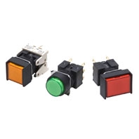
Separate Construction with Cylindrical 16-dia. Body
Related Contents
last update: November 10, 2025
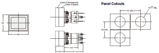
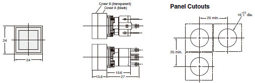
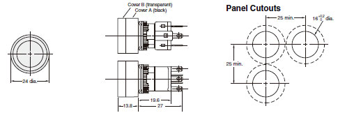
(Unit: mm)
• The Dimension shows 2-switch outputs.
• The lamp terminal is also provided with non-lighted models.
Rectangular
A16[]-J
Solder terminals and tab terminals (#110 t=0.5)
See below for panel cutouts
Square
A16[]-A
Solder terminals and tab terminals (#110 t=0.5)
See below for panel cutouts
Round
A16[]-T
Solder terminals and tab terminals (#110 t=0.5)
See below for panel cutouts
• The Dimension shows 2-switch outputs.
• The lamp terminal is also provided with non-lighted models.
• A rectangular model is listed as an example.
Rectangular
A16[]-J[]-[]P
PCB terminals
See below for panel cutouts
Rectangular
A16[]-J[]-T1
Voltage-reduction lighting, solder terminals and tab terminals (#110 t=0.5)
Rectangular
A16[]-J[]-2S, T1-2S, T2-2S
Screw-less Clamp
Lamps
LED
A16-5D[]/-12D[]/-24D[]
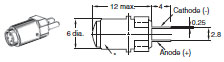
* The voltage display surface is the same color as the illumination color. The opposite surface is light gray.
(For pure white, the entire surface is light gray.)
(For pure white, the entire surface is light gray.)
Accessories, Tools, and Components
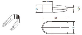
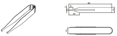
Extractor
A3PJ-5080
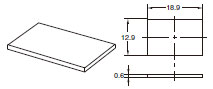
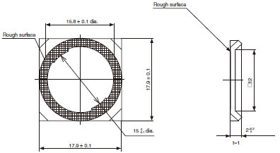
Legend Plates
A16ZJ-5204
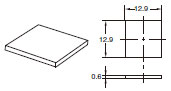
A16ZA-5204
A16ZT-5204
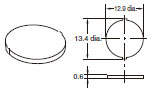
Note: The panel is 0.6 mm thick.
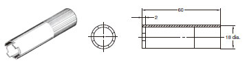
Screw Fitting
A16Z-3004
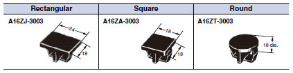
Panel Plugs (Black Resin)
Select the Plug that fits the panel design and mount from the front of the Panel. Panel cutouts are the same as those for Switches.
Protective structure: IP40
Color: Black
Lock Ring
Socket Unit Lamp Extractor
A16Z-5080
Panel Cutouts
Solder Terminals and Screw-less Clamp Connectors
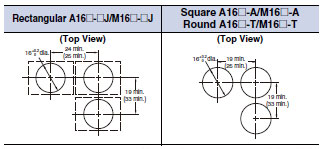
Note:• Make sure the thickness of the mounting panel is between 0.5 and 3.2 mm. If, however, a Switch Guard or Dust
Cover is used, the thickness of the mounting panel must be between 0.5 and 2 mm.
• If the panel is to be finished with coating, etc., make sure that the panel meets the specified dimensions after
coating.
• Figures in parentheses are for Screw-less Clamp Connectors.
Cover is used, the thickness of the mounting panel must be between 0.5 and 2 mm.
• If the panel is to be finished with coating, etc., make sure that the panel meets the specified dimensions after
coating.
• Figures in parentheses are for Screw-less Clamp Connectors.
PCB Terminals
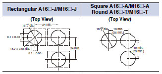
Note:• Ensure that the variation in the distance between the centers of neighboring mounting holes is less than ±0.1
mm.
• Make sure the thickness of the mounting panel is between 0.5 and 3.2 mm. If, however, a Switch Guard or Dust
Cover is used, the thickness of the mounting panel must be between 0.5 and 2 mm.
• If the panel is to be finished with coating, etc., make sure that the panel meets the specified dimensions after
coating.
Accessory Dimensions Mounted
Dimensions with Switch Guard Installed
Rectangular
A16ZJ-5050
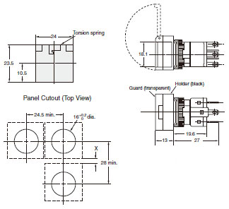
Note: This example is for when X is 4.5 mm.
If X is not required, the Switches can be mounted with a minimum vertical installation pitch of 24 mm min.
If X is not required, the Switches can be mounted with a minimum vertical installation pitch of 24 mm min.
Square
A16ZA-5050
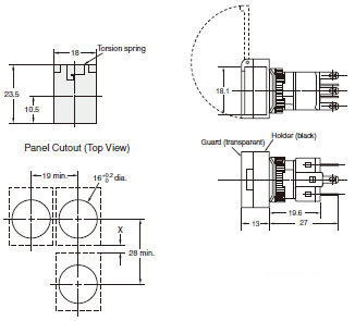
Note: This example is for when X is 4.5 mm.
If X is not required, the Switches can be mounted with a minimum vertical installation pitch of 24 mm min.
If PCB terminals are used, provide X must be 24 mm or larger.
If X is not required, the Switches can be mounted with a minimum vertical installation pitch of 24 mm min.
If PCB terminals are used, provide X must be 24 mm or larger.
Dust Covers
Rectangular
A16ZJ-5060
Square
A16ZA-5060
Round
A16ZT-5060
last update: November 10, 2025