Discontinued On Jan. 2026
H3CA
Solid-state Timer
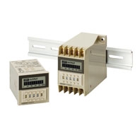
DIN-sized (48 × 48, 45 × 75 mm) Timer with Digital Setting and LCD Display
* Information in this page is a reference that you created on the basis of information in the product catalog before the end of production, may be different from the current situation, such as goods for / supported standards options / price / features of the product. Before using, please check the compatibility and safety system.
Related Contents
- Features
- Lineup
- Specifications
- Dimensions
- Catalog / Manual / CAD / Software
last update: February 9, 2018
Time Ranges
A desired time can be set within a range of 0.1 s to 9,990 hrs by combining the three thumbwheel switch modules for time setting and one module for time unit selection.
| Time unit | 0.1 s | 1 s | 0.1 min | 1 min | 0.1 hrs | 1 hr | 10 hrs | |
|---|---|---|---|---|---|---|---|---|
| Time range | 1 to 999 (3 digits) |
 |
||||||
Ratings
| Item | H3CA-A/H3CA-FA | H3CA-8 | H3CA-8H |
|---|---|---|---|
| Rated supply voltage
*2 |
24 to 240 VAC (50/60 Hz),
12 to 240 VDC (permissible ripple: 20% max.) |
100/110/120, 200/220/240 VAC, (50/60 Hz), 24 VDC,
110 VDC (permissible ripple: 20% max.) *1 |
|
| Operating voltage range | 90% to 110% of rated supply
voltage |
85% to 110% of rated supply voltage | |
| Power consumption | AC: approx. 4 VA
DC: approx. 2 W |
AC: approx. 10 VA/1 W
DC: approx. 1 W |
AC: approx. 10 VA/1.5 W
DC: approx. 2 W |
| Control outputs | 3 A at 250 VAC, resistive load (cosφ = 1)
Minimum applicable load H3CA-8, H3CA-A and H3CA-FA: 10 mA at 5 VDC (failure level: Preference value) H3CA-8H: 100mA at 5 VDC (failure level: Preference value) Contact materials: Ag-alloy |
||
*1. Single-phase, full-wave rectified power sources may be used for 24 to 240 VDC.
*2. Refer to Safety Precautions for All Times when combining the Timer with an AC 2-wire proximity sensor.
Characteristics
| Accuracy of operating time | ±0.3% ±0.05 s |
|---|---|
| Influence of voltage | |
| Influence of temperature | |
| Setting error | ±0.5% ±0.05 s max. |
| Reset time | H3CA-A/-FA: 0.5 s max.
H3CA-8H/-8: 0.1 s max. |
| Insulation resistance | 100 MΩ min. (at 500 VDC) |
| Dielectric strength | 2,000 VAC, 50/60 Hz for 1 min (between current-carrying and non-current-carrying parts
and between contact and control circuit) 1,000 VAC, 50/60 Hz for 1 min (between non-continuous contacts) |
| Impulse withstand voltage | A wide AC/DC power supply range, 200/220/240 V specifications
Between power terminals: 5 kV, Between current-carrying terminal and exposed non- current-carrying metal parts: 5 kV 100/110/120 VAC, 100/110 VDC specifications Between power terminals: 3 kV, Between current-carrying terminal and exposed non- current-carrying metal parts: 4.5 kV 24 VDC specifications Between power terminals: 1 kV, Between current-carrying terminal and exposed non- current-carrying metal parts: 1.5 kV |
| Vibration resistance | Destruction: 10 to 55 Hz with 0.75-mm double amplitude for 1 h each in three directions
Malfunction: 10 to 55 Hz with 0.5-mm double amplitude for 10 min each in three directions |
| Shock resistance | Destruction: 980 m/s2
Malfunction: 98 m/s2 |
| Ambient temperature | Operating: -10°C to 55°C |
| Ambient humidity | Operating: 35% to 85% |
| Life expectancy | Mechanical: 10,000,000 operations min. (under no load at 1,800 operations/h)
Electrical: 100,000 operations min. (3 A at 250 VAC, cosφ = 1 at 1,800 operations/h) See Lift-test Curve for more details. |
| Approved standards | UL508, CSA C22.2 No. 14, LR, NK
Conforms to EN61812-1. |
| EMC | (EMI) EN61812-1
Emission Enclosure: EN55011 Group 1 class A Emission AC mains: EN55011 Group 1 class A (EMS) EN61812-1 Immunity ESD: IEC61000-4-2 Immunity RF-interference: IEC61000-4-3 Immunity Burst: IEC61000-4-4 Immunity Surge: IEC61000-4-5 Immunity Conducted Disturbance: IEC61000-4-6 Immunity Voltage Dip/Interruption: IEC61000-4-11 |
| Weight | H3CA-A: approx. 110 g
H3CA-FA: approx. 190 g |
last update: February 9, 2018
 Product Category
- Control Components
-
Timers
-
Discontinued
- H3CA
-
Discontinued
-