H3FA
Solid-state Timer
DIP Model Timer for PC Board Use Provides Contact and Solid-state Output
Related Contents
- Features
- Lineup
- Specifications
- Dimensions
- Catalog / Manual / CAD / Software
last update: August 1, 2016
Time Ranges
| Model | Rated time | Time setting range |
|---|---|---|
| H3FA-A | 1 s | 0.1 to 1 s |
| H3FA-AU | 10 s | 1 to 10 s |
| H3FA-SA | 1 min | 0.1 to 1 min |
| H3FA-SAU | 10 min | 1 to 10 min |
| H3FA-B | 6 s | 0.6 to 6 s |
| H3FA-BU | 60 s | 6 to 60 s |
| H3FA-SB | 6 min | 0.6 to 6 min |
| H3FA-SBU | 60 min | 6 to 60 min |
Note: 1. The above timing ranges apply when the internal variable resistor of H3FA is used.
2. The external variable resistor may also be used by opening the terminal connected to the internal variable
resistor.
3. Wire the appropriate terminal to select a time setting range. Refer to Rated Time and Terminal Connections on
Data Sheet for details.
2. The external variable resistor may also be used by opening the terminal connected to the internal variable
resistor.
3. Wire the appropriate terminal to select a time setting range. Refer to Rated Time and Terminal Connections on
Data Sheet for details.
Ratings
| Item | H3FA-A/ H3FA-B
H3FA-AU/ H3FA-BU |
H3FA-SA/ H3FA-SB
H3FA-SAU/ H3FA-SBU |
|---|---|---|
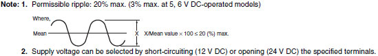
| Rated supply voltage | 5 V DC, 6V DC, 12V DC, 24 V DC *1 | 5/6 V DC *1
12/24 V DC *1, *2 |
| Operating voltage range | 5 V DC: 90% to 110% of rated supply voltage
6, 12, 24 V DC: 85% to 110% of rated supply voltage |
|
| Power consumption | 5, 6 V DC: approx. 230 mW
12 V DC: approx. 270 mW 24 V DC: approx. 330 mW |
5/6 V DC: approx. 80 mW
12 V DC: approx. 100 mW 24 V DC: approx. 240 mW |
| Control outputs | Contact output: SPST-NO + SPST-NC,
3 A at 250 V AC with resistive load, Minimum applied load: 10 mA at 5 V DC (Failure level: P, reference value) |
Solid-state output: 150 mA max. at 30 V DC
Residual voltage: 1.0 V max. |
| Ambient temperature | Operating: -10°C to 55°C (with no icing)
Storage: -25°C to 65°C (with no icing) |
|
| Ambient humidity | 35% to 85% | |
Characteristics
| Accuracy of operating
time |
±0.5% FS max. *1, *3 |
|---|---|
| Setting error | 0 to 30 % FS max. (at 20°C , at rated voltage) |
| Reset time | 10 ms max. |
| Influence of voltage | ±1% FS max. (2% FS max. for 5, 6, 5/6 V DC-operated models) |
| Influence of temperature | ±5% FS max. *1 |
| Insulation resistance | 100 MΩ min. (at 500 V DC) |
| Dielectric strength | 1,500 V AC, 50/60 Hz for 1 min (between control output and operating circuit) *2
1,000 V AC, 50/60 Hz for 1 min (between contacts not located next to each other) *2 |
| Vibration resistance | Destruction: 10 to 55 Hz with 0.375-mm single amplitude in 3 directions for 2 hour each
Malfunction: 10 to 55 Hz with 0.25-mm single amplitude in 3 directions for 10 minutes each |
| Shock resistance | Destruction: 1,000 m/s2 3 times each in 6 directions on 3 axes
Malfunction: 100 m/s2 3 times each in 6 directions on 3 axes |
| Life expectancy | Mechanical: 10,000,000 operations min. (under no load at 1,800 operations/h) *2
Electrical: 100,000 operations min. (3 A at 250 V AC, resistive load at 1,800 operations/h) *2 |
| Approved safety
standards |
UL508, CSA C22.2 No.14 |
| Weight | Contact output models: approx. 15 g
Solid-state output models: approx. 10 g |
*1. Add or subtract 10 ms to the ratings when using a timer with a rated time of 1 s.
*2. Applicable to contact output models.
*3. This value assumes that the adjustment on the H3FA is used. (It does not apply if an externally connected resistor is
used. For details, refer to External Resistors and Operating Time (Reference Value) on Data Sheet for details.)
*2. Applicable to contact output models.
*3. This value assumes that the adjustment on the H3FA is used. (It does not apply if an externally connected resistor is
used. For details, refer to External Resistors and Operating Time (Reference Value) on Data Sheet for details.)
last update: August 1, 2016