H5S
Digital Time Switch
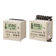
Easier, More Convenient Time Switches, with New 4-circuit Output and Yearly Models in Addition to 2-circuit Weekly Models
Related Contents
- Features
- Lineup
- Specifications
- Dimensions
- Catalog / Manual / CAD / Software
last update: November 1, 2024
Ratings
| Item | Weekly 2-circuit
Models (H5S-W[]2) |
Yearly 2-circuit
Models (H5S-Y[]2) |
Yearly 4-circuit
Models (H5S-Y[]4) |
||
|---|---|---|---|---|---|
| Rated supply voltage | 100 to 240 VAC (50/60 Hz), 24 VDC *1 | ||||
| Operating voltage range | AC: 85% to 110% rated supply voltage
DC: 85% to 120% rated supply voltage |
||||
| Power consumption | Approx. 2.9 VA at 264 VAC
60 Hz Approx. 0.8 W at 28.8 VDC |
Approx. 3.2 VA at 264 VAC
60 Hz Approx. 0.9 W at 28.8 VDC |
Approx. 3.5 VA at 264 VAC
60 Hz Approx. 1.0 W at 28.8 VDC |
||
| Control
outputs |
Number of circuits | SPST-NO × 2 circuits | SPST-NO × 4 circuits | ||
| Circuits | Power supply circuit and other (no-voltage) circuit | ||||
| Ca-
pacity |
Resistive load
(cosφ = 1) |
15 A at 250 VAC *2 | 3 A at 250 VAC | ||
| Inductive load | 10 A at 250 VAC (cosφ = 0.7) | 2 A at 250 VAC
(cosφ = 0.4) |
|||
| Ambient operating temperature | -10 to 55°C (with no icing or condensation) | ||||
| Ambient operating humidity | 25 to 85% | ||||
| Storage temperature | -25 to 65°C (with no icing or condensation) | ||||
| Case color | Light gray (Munsell 5Y7/1) | ||||
*1. Do not use inverter output as a power supply. For details, refer to Precautions for Safe Use, item 24, on Data Sheet.
*2. The capacity is 15 A per circuit, but derating of the total current for two circuits is required
*2. The capacity is 15 A per circuit, but derating of the total current for two circuits is required
Characteristics
| Item | Weekly 2-circuit Models
(H5S-W[]2) |
Yearly 2-circuit Models
(H5S-Y[]2) |
Yearly 4-circuit Models
(H5S-Y[]4) |
|
|---|---|---|---|---|
| Accuracy of operating
time |
±0.01%±0.05 s max. *1
The ±0.01% value applies to the set time interval. |
|||
| Setting error | ||||
| Influence of voltage | ||||
| Influence of temperature | ||||
| Cyclic error | ±15 s per month (at 25°C) | ±15 s per month (at -10 to 45°C), ±20 s per month (at
45 to 55°C) |
||
| Memory protection | Continuous use: 5 years min. (at 25°C) *2 | |||
| Insulation resistance | 100 MΩ min. (between current-carrying terminals and exposed non-current carrying metal parts, between operation circuit and control output circuit, between control output circuits, and between non-continuous contacts.) | |||
| Dielectric strength | 2,950 VAC, 50/60 Hz for 1 min (between current-carrying terminals and exposed non-current carrying metal parts)
2,000 VAC, 50/60 Hz for 1 min (between operation circuit and control output circuit, and between control output circuits) 1,000 VAC, 50/60 Hz for 1 min (between non-continuous contacts) |
|||
| Noise immunity | ±1,500 V (between power terminals, for AC power models), ±500 V (between power terminals, for DC power models)
Square-wave noise by noise simulator (pulse width: 100 ns, for 1 μs, 1-ns rise time) |
|||
| Vibration
resistance |
Destruction | 10 to 55 Hz with 0.375-mm single amplitude in 3 directions for 2 hours each | ||
| Malfunction | 10 to 55 Hz with 0.25-mm single amplitude in 3 directions for 10 minutes each | |||
| Shock
resistance |
Destruction | 300 m/s2 3 times each in x, y, and z axes, 6 directions | ||
| Malfunction | 100 m/s2 3 times each in x, y, and z axes, 6 directions | |||
| Life
expectancy |
Mechanical | 100,000 operations min. | ||
| Electrical | 50,000 operations min. (15 A at 250 VAC, resistive load)
50,000 operations min. (10 A at 30 VDC, resistive load) 50,000 operations min. (10 A at 250 VAC, inductive load (cosφ = 0.7)) 50,000 operations min. (1 HP at 250 VAC, motor load) 50,000 operations min. (100 W at 100 VAC, lamp load) 10,000 operations min. (300 W at 100 VAC, lamp load) |
50,000 operations min. (3 A
at 250 VAC, resistive load) 50,000 operations min. (3 A at 30 VDC, resistive load) |
||
| Degree of protection | Compliant with IEC IP40 for panel surface only, Certified for UL Type 1 | |||
| Approved standards | CURUS: UL 508/CSA C22.2 No.14,
Conforms to EN 60730-2-7(Pollution degree 2/overvoltage category II), Conforms to VDE 0106/part100. Conforms to Electrical Appliance and Material Safety Law (for Japan) |
|||
| EMC | (EMI) EN 60730-2-7
EMI Radiated: EN 60730-2-7 (CISPR 22 Class B) EMI Conducted (Continuous): EN 60730-2-7 (CISPR 22 Class B) EMI Conducted (Non-continuous): EN 60730-2-7 (CISPR 14-1) Harmonic Current: EN 60730-2-7 (IEC 61000-3-2 Class A) Voltage fluctuation/flicker: EN 60730-2-7 (IEC 61000-3-3) (EMS) EN 60730-2-7 ESD Immunity: EN 60730-2-7 (IEC 61000-4-2): 6 kV contact discharge, 8 kV air discharge Radiated Electromagnetic Field Immunity: EN 60730-2-7 (IEC 61000-4-3): 10-V/m AM modulation (80 MHz to 1 GHz, 1.4 GHz to 2 GHz), 10-V/m pulse modulation (900 MHz) Conducted Disturbance Immunity: EN 60730-2-7 (IEC 61000-4-6): 10 V (0.15 to 80 MHz) Burst Immunity: EN 60730-2-7 (IEC 61000-4-4): 2 kV power line, 1 kV control line Surge Immunity: EN 60730-2-7 (IEC 61000-4-5): 1 kV line to line (power line, output line), 2 kV line to ground (power line, output line), 0.5 kV line to line (input line), 1 kV line to ground (input line) Voltage Dip/Interrupting Immunity: EN 60730-2-7 (IEC 61000-4-11): 0.5-s cycle, 100% (rated voltage) |
|||
| Weight | Approx. 200 g | |||
*1. The total error including the repeat accuracy, setting error, variation due to voltage change, and variation due to
temperature change is ±0.01% ±0.05 s max.
*2. The time given for memory protection is the calculated time of when power is not being supplied (including during
storage) at an ambient temperature of 25°C. The timer functions and set program are backed up by a lithium battery
that is built into the Time Switch. These will be lost if the life of the battery expires. If the lithium battery is replaced
(if the PCB is replaced), the stored contents will also be lost.
Operation
| Item | Weekly 2-circuit
Models (H5S-W[]2) |
Yearly 2-circuit
Models (H5S-Y[]2) |
Yearly 4-circuit
Models (H5S-Y[]4) |
|
|---|---|---|---|---|
| Operation method | Digital quartz | |||
| Operation period | 1 week (7 days) | 1 year (with integrated calendar to 2099) | ||
| Display | Day, hrs (switchable between 24-hr indication and a.m./p.m. 12-hr indication),
minutes, seconds (0.00 to 23:59, 0.00 to 11:59 a.m., 0.00 to 11:59 p.m.) Digital indication by LCD (character height: 10 mm) Digital display of operation schedule during operation Timing chart display of operation schedule during operation |
|||
| Min. setting unit | 1 min | |||
| Number of
steps that can be set |
Weekly program
*1 |
40 steps/circuit | 48 steps/circuit *2
24 steps/circuit (per season) *3 |
48 steps/circuit *2
12 steps/circuit (per season) *3 |
| Yearly program | --- | 4 yearly programs/circuit | ||
| Number of settable
yearly temporary holiday settings |
--- | 16 | ||
*1. Depending the operation, the following steps can be used for weekly programs.
Timer operation: 2 steps
Pulse-output operation: 1 step
Cyclic operation: 4 steps
*2. When the season switching setting is not being used.
*3. When the season switching setting is being used.
Timer operation: 2 steps
Pulse-output operation: 1 step
Cyclic operation: 4 steps
*2. When the season switching setting is not being used.
*3. When the season switching setting is being used.
Operation Functions
| Item | Weekly 2-circuit Models
(H5S-W[]2) |
Yearly 2-circuit Models
(H5S-Y[]2) |
Yearly 4-circuit Models
(H5S-Y[]4) |
|---|---|---|---|
| Weekly timer
operation |
 Min. setting unit: 1 min Multiple-day operation also possible. |
||
| Weekly pulse-output
operation |
 Pulse width: 1 to 59 s (in 1-s increments), or 1 to 60 min (in 1-min increments) The pulse width can be set for each step. |
||
| Weekly cyclic
operation |
 Independent ON- and OFF-time settings are possible. Min. setting unit: 1 min (The ON time width and OFF time width can each be set to between 1 minute and 11 hours 59 minutes.) (The timer operation repeatedly turns the signal ON and OFF for the time widths specified by the ON time and OFF time during the period from the day of the week and time that are set for the cyclic start time to the day of the week and time that are set for the stop time.) |
||
| Yearly timer operation | --- | Adds a yearly timer operation to the weekly timer program.
For details, refer to About Yearly Programs on Data Sheet. |
|
| Yearly pulse-output
operation |
--- | Adds a yearly pulse-output operation to the weekly
pulse-output program. For details, refer to About Yearly Programs on Data Sheet. |
|
| Temporary holiday
setting |
Sets temporary holidays (non-operating days) without having to revise the existing program.
For details, refer to Setting Temporary Holidays (Weekly) and Setting Temporary Holidays (Yearly) on Data Sheet. |
||
| Day override operation | Executes the operation for
one day temporarily on another day in the 7-day period starting from the current day. For details, refer to Day Override Operation on Data Sheet. |
--- | |
| Program check | Consecutively displays the days and times when the output is set to turn ON and OFF over
the course of one week in the sequence in which the Time Switch is to operate. For details, refer to Program Check Function on Data Sheet. |
||
| Checking the settings | Consecutively displays the times when the output is set to turn ON and OFF for one day in
the sequence in which the Time Switch is to operate. For details, refer to Checking the Settings on Data Sheet. |
||
| Forced ON/OFF
operation |
Allows the output to be forcibly turned ON/OFF by the Output ON/OFF Switch regardless of
the control output setting. |
||
| Override and automatic
return operation |
Allows the control output to be maintained in the ON (or OFF) state until the next OFF (or
ON) time. This operation is controlled by using the Output ON/OFF Switch and Write Key. When completed, the Time Switch automatically resumes the previously set operation. For details, refer to Override and Automatic Return Operation on Data Sheet. |
||
| Summertime (DST)
adjustment |
Switches the current time from "current time" to "current time + 1 h" for daylight savings
time. Yearly models also offer automatic switching to daylight savings time. For details, refer to Manual Summer Time (DST) Adjustment on Data Sheet. |
||
| Time counter/total
counter display |
Displays the total elapsed time and total count of external
input. It also displays a warning when a set value is entered. For details, refer to Time Counter/Total Counter Display (F2, F3, F4) on Data Sheet. |
--- | |
| Time adjustment input | Allows the time to be set to 00 min 00 s at the same time as
an external input is applied. For details, refer to Time Adjustment Input Function (F2) on Data Sheet. |
--- | |
| Manual operation on
recovery from power failure |
Allows the output state to be specified following recovery
from a power failure. For details, refer to Manual Operation on Recovery from Power Failure (F2) on Data Sheet. |
--- | |
| Bank switching | Allows two groups (banks) of
programs to be registered and switched by external input. For details, refer to Bank Switching (F2) on Data Sheet. |
--- | |
| Season switching | --- | Allows weekly programs to be automatically switched in
response to seasons throughout the year. For details, refer to Season Switching/Period of Season (F8/F9) on Data Sheet. |
|
| Power OFF settings | Allows the display to remain lit even when the power is turned OFF, and settings to be made
for all functions except Override and Automatic Return Operation. The display illumination will turn OFF when there has been no operation for 2 min. The display will light again when any key other than a slide switch is pressed for at least 1 s. No output will be generated. |
||
last update: November 1, 2024