CK3A-G305L / -G310L / -G320L
CK3A-series Direct PWM Amplifier
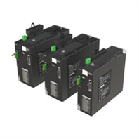
This servo amplifier provides ultra-low latency servo control by taking signals directly from the controller and flexibility to connect to various motors and encoders
Related Contents
- Features
- Lineup
- Specifications
- Dimensions
- Catalog / Manual / CAD / Software
last update: April 1, 2025
General/Mechanical
| Item | Specification | |
|---|---|---|
| Number of axes | 1 | |
| Enclosure | Panel mount | |
| Protective case | IP20 (built into IP54 panel) | |
| Grounding | 200 V class D grounding, 100 Ω or less | |
| Vibration resistance | 10 to 60 Hz at an acceleration of 5.88 m/s2 or less
(Not to be run continuously at the resonant frequency) |
|
| Air flow clearance | Refer to installation section | |
| Mounting screws tightening torque | 1.2 Nm | |
| Cooling | Natural convection and built-in fan | |
| Weight | CK3A-G305L | 1.81 kg |
| CK3A-G310L | 2.67 kg | |
| CK3A-G320L | 2.77 kg | |
| Dimensions | CK3A-G305L | 212.5 x 65.0 x 180.0 mm |
| CK3A-G310L | 238.0 x 90.0 x 180.0 mm | |
| CK3A-G320L | 238.0 x 90.0 x 180.0 mm | |
| Regulations
and Standards |
Conformance to
EU Directives |
EMC Directive: EN61800-3 second environment
Low Voltage Directive: EN61800-5-1 C2 category Functional Safety: EN61800-5-2 SIL3 (STO) |
| Conformance to
UL Directives |
UL Standards: UL 61800-5-1
CSA Standards: CSA C22.2 No. 274 |
|
| Conformance to
UKCA Standards |
UKCA: 2016 No. 1091
UKCA: 2016 No. 1101 EMC Directive: 2016 No. 1091 Low Voltage Directive: 2016 No. 1101 Functional Safety: 2008 No. 1597 |
|
| Conformance to
KC Standards |
Immunity Standard for Industrial Environments: KS C 9610-6-2
Emission Standard for Industrial Environments: KS C 9610-6-4 |
|
Environmental
| Item | Specification |
|---|---|
| Operating ambient temperature | 0 to 55 °C |
| Operating ambient humidity | 10 to 90% RH (without condensation or icing) |
| Storage ambient temperature | -25 to 70 °C |
| Storage ambient humidity | 10 to 90% RH (without condensation or icing) |
| Operating and storage atmosphere | Must be free of corrosive gases |
| Maximum operating altitude | 2,000 m |
| Pollution Degree | 2 |
Electrical
The following section details the key electrical specifications for each of the CK3A-G3[][]L Amplifiers.
| Item | CK3A-G305L | CK3A-G310L | CK3A-G320L | ||
|---|---|---|---|---|---|
| Logic power
supply |
Voltage | 24 VDC *1 | |||
| Current consumption | 1.5 A | ||||
| Inrush current | 2.5 A | ||||
| Inrush time | 5 msec | ||||
| Main circuit
power supply |
3-Phase AC | Voltage | 240 VAC ± 5 °C *2 | ||
| F.L.A. | 6 Arms | 11 Arms | 18 Arms | ||
| Frequency | 50 / 60 Hz | ||||
| 1-Phase AC | Voltage | 240 VAC ± 5% *2
110 VAC ± 5% *3 |
240 VAC ± 5% *2, *7 | ||
| F.L.A. | 10.5 Arms | 19.5 Arms | 28 Arms | ||
| Frequency | 50 / 60 Hz | ||||
| 1-Phase DC *4 | Voltage | 48 VDC *5 | - | 100 VDC ± 10% *6 | |
| F.L.A | 6 A | - | 19 A | ||
| Output | Rated Current | 5 ARMS | 10 ARMS | 20 ARMS | |
| Maximum (peak) Current | 10 ARMS | 20 ARMS | 60 ARMS | ||
| Maximum Rated Power
(3-Phase AC) |
1195 W | 2390 W | 4400 W | ||
| Maximum Rated Power
(1-Phase 240 VAC) |
1195 W | 2390 W | 4400 W | ||
| Maximum Rated Power
(1-Phase 110 VAC) |
550 W | 1095 W | - | ||
| Maximum Rated Power
(1-Phase DC) |
195 W | - | 1600 W | ||
| Time at Peak Current | 2 sec | ||||
| PWM Interface | Current feedback resolution | 16 bits | |||
| Maximum current ADC reading | 15.735 A | 31.470 A | 93.844 A | ||
| Minimum PWM deadtime | 2 μsec | 3 μsec | |||
| PWM Frequency | 8 to 20 kHz | 8 to 16 kHz *8 | |||
| Shunt Resistor | Internal shunt resistor | 25 Ω, 30 W | 17 Ω, 80 W | 17 Ω, 80 W | |
| External shunt resistor | 20 Ω, 60 W | 17 Ω, 60 W | 17 Ω, 60 W | ||
*1. The range of acceptable variation for the Logic Power Supply input voltage is 22.0 to 26.4 VDC.
*2. The range of acceptable variation for this Main Circuit input voltage is 170 to 252 VAC.
*3. The range of acceptable variation for this Main Circuit input voltage is 85 to 170 VAC.
*4. All models require the ADC Strobe Word set to operate with low voltage (1-Phase DC) main power input.
*5. The range of acceptable variation for this Main Circuit input voltage is 44 to 60 VDC.
*6. The range of acceptable variation for this Main Circuit input voltage is 90 to 110 VDC.
*7. The CK3A-G320L may require derating on maximum rated power with some (1-Phase AC) Main Circuit input voltages. Refer to the diagram below showing the derating amount at 25°C.
*8. The CK3A-G320L may require derating on maximum rated power if PWM frequency over 10 kHz is used. Refer to the diagram below showing the derating amount.
Note: 1. In addition to configuring the ADC Strobe Word, the CK3A-G310L requires a special part number and factory modification to operate with low voltage (48 VDC) main power input. Contact your local Omron representative for this option.
Power Output De-Rating by 1-Phase Input Voltage (CK3A-G320L Only)
Power Output De-Rating by PWM Frequency (CK3A-G320L Only)
Performance
| Specification | Value | Notes |
|---|---|---|
| STO input to power drivers OFF | < 150 msec | |
| Overcurrent I2T to IPM OFF | < 10 msec | A8 fault |
| Phase short to IPM OFF | < 3 μsec | AC fault |
| Current loop response time | < 1 msec | 1 mH 3-Ph brushless Motor Y-winding |
| Dynamic brake relay response time | < 20 msec | Mechanical relay time constant |
| I2T time to Amplifier OFF | < 2.5 sec | CK3A-G305L: At 200% output
CK3A-G310L: At 200% output CK3A-G320L: At 300% output |
| Soft start time | < 650 msec | Do not enable Amplifier during soft start |
| Hold at momentary power interruption | 10 msec | 3-ph 208VAC @ rated load |
| DC Bus discharge time with bus discharge ON
(Discharge to less than 36 VDC) |
< 2.5 sec | Forced discharge to shunt resistor |
| DC Bus discharge time with bus discharge OFF
Discharge to less than 36 VDC) |
< 5 min | Natural discharge, CK3A-G305L |
| < 5 min | Natural discharge, CK3A-G310L | |
| < 6 min | Natural discharge, CK3A-G320L | |
| Current ADC clock frequency range | 2.450 to 6.250 MHz | Set in Controller |
| Time between main circuit power cycles
with bus discharge ON |
1 min minimum | To prevent overloading the soft start or discharge circuitry |
| Time between main circuit power cycles
with bus discharge OFF |
10 sec minimum | To prevent overloading the soft start circuitry |
Amplifier Internal Regeneration Absorption Capacity
The following table shows the Amplifier power, internal shunt resistor specifications, regenerative power absorption capacity and maximum duration. These values are based on a 200VAC main power supply.
| Model | CK3A-G305L | CK3A-G310L | CK3A-G320L |
|---|---|---|---|
| Rated RMS power [W] | 1195 W | 2390 W | 4400 W |
| Internal shunt resistor specification | 25 Ω 30 W | 17 Ω 80 W | |
| Built-in capacitors absorption energy [J] | 46 J | 62 J | |
| Internal shunt resistor average regeneration energy [W] | 18 W | 32 W | |
| Maximum duration of continuous regeneration [sec] | 2 sec | 2 sec | |
| Minimum allowable shunt resistance [Ω] | 20 Ω | 15 Ω | 15 Ω |
last update: April 1, 2025