G9H
Hybrid Power Relay
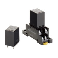
Hybridization of a Magnetic Relay and an SSR Achieves 10-A Switching for 10 Million Operations.
Related Contents
- Features
- Lineup
- Specifications
- Dimensions
- Catalog / Manual / CAD / Software
last update: February 10, 2025
Ratings
Input
|
Rated voltage |
Item | Operating voltage |
Coil resistance |
Must operate voltage |
Must release voltage |
Power consumption |
|---|---|---|---|---|---|---|
| DC | 5 V | 4 to 6 VDC | 104 Ω | 4 VDC max. | 0.5 VDC min. | Approx. 240 mW |
| 12 V | 9.6 to 14.4 VDC | 600 Ω | 9.6 VDC max. | 1.2 VDC min. | ||
| 24 V | 19.2 to 28. 8 VDC | 2,400 Ω | 19.2 VDC max. | 2.4 VDC min. |
Note: 1. The coil resistance is measured at a coil temperature of 23°C with a tolerance of ±10%.
2. Performance characteristic data are measured at a coil temperature of 23°C.
2. Performance characteristic data are measured at a coil temperature of 23°C.
Output
| Item | Applicable load | |||
|---|---|---|---|---|
| Model | Rated load
voltage |
Load voltage
range |
Load current
(See note.) |
Inrush current resistance |
| G9H-205S-US | 100 to 240 VAC | 75 to 264 VAC | 50 mA to 5 A (at 55°C) | 80 A (60 Hz, 1 cycle) |
| G9H-210S-US | 50 mA to 10 A (at 55°C) | 170 A (60 Hz, 1 cycle) | ||
Note: The load current depends on the ambient temperature. For details, refer to Load Current vs. Ambient Temperature
in Engineering Data.
in Engineering Data.
Characteristics
| Item | G9H-205S-US | G9H-210S-US | |
|---|---|---|---|
| Operate time | 10 ms max. | ||
| Release time | 1/2 cycle max. + 10 ms | ||
| Output ON voltage drop | 1.6 V max. (RMS) (at 5 A) | 1.6 V max. (RMS) (at 10 A) | |
| Leakage current | 5 mA max. at 250 VAC | ||
| Inrush current resistance | 80 A | 170 A | |
| Temperature rise | 50°C max. (rated voltage applied using resistance method) | ||
| Insulation resistance | 100 MΩ min. (at 500 VDC) | ||
| Dielectric strength | 2,000 VAC 50/60 Hz 1 min | ||
| Vibration
resistance |
Destruction | 10 to 55 to 10 Hz, 0.75-mm single amplitude (1.5-mm double amplitude) | |
| Malfunction | 10 to 55 to 10 Hz, 0.75-mm single amplitude (1.5-mm double amplitude) | ||
| Shock resistance
(See note.) |
Destruction | 1,000 m/s2 | |
| Malfunction | 100 m/s2 | ||
| Life expectancy | Mechanical | 10 million operations min. (switching frequency: 18,000 operations/hour) | |
| Electrical | 10 million operations min. (resistive load and switching frequency: 18,000 operations/hour) | ||
| Storage temperature | -25 to 70°C (with no icing or condensation) | ||
| Ambient operating temperature | -25 to 60°C (with no icing or condensation) | ||
| Ambient operating humidity | 35% to 85% | ||
| Weight | Approx. 25 g | ||
Note: Value when excited.
Accessories (Order Separately)
Socket Characteristics
| Model | Rated
carry current |
Dielectric strength | Insulation
resistance *1 |
Remarks |
|---|---|---|---|---|
| PTF-08-PU | 10 A | Between contact terminals of different polarity: 2,000 VAC, 1 min | 1,000 MΩ min. | |
| Between contact terminals of same polarity: 2,000 VAC, 1 min | ||||
| Between coil and contact terminals: 2,000 VAC, 1 min | ||||
| PTFZ-08-E | 12 A
(@70°C) *2 |
Between contact terminals of different polarity: 2,500 VAC, 1 min | 1,000 MΩ min. | |
| Between contact terminals of same polarity: 2,500 VAC, 1 min | ||||
| Between ground terminals: 2,500 VAC, 1 min | ||||
| Between coil and contact terminals: 2,500 VAC, 1 min | ||||
| PTF08A | 10 A | Between terminals: 2,000 VAC for 1 min | 100 MΩ min. | |
| PT-08 | 10 A | Between terminals: 2,000 VAC for 1 min | 100 MΩ min. | |
| PT08-0 | 10 A | Between terminals: 2,000 VAC for 1 min | 100 MΩ min. | |
| PT08QN | 10 A | Between terminals: 2,000 VAC for 1 min | 100 MΩ min. |
*1 The insulation resistance was measured with a 500-VDC insulation resistance meter at the same places as those used for measuring the dielectric strength.
*2 However, do not exceed the continuous carry current of the socket to be mounted.
last update: February 10, 2025