i4L
SCARA Robot
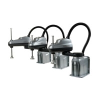
New i4L robot for precision machining, assembly, and material handling
ACE software is available to download from the Omron US website.
Related Contents
- Features
- Lineup
- Specifications
- Dimensions
- Catalog / Manual / CAD / Software
last update: March 2, 2026
| Product | i4-350L | i4-450L | i4-550L | ||
|---|---|---|---|---|---|
| Quill Length | 180 mm | 180 mm | 180 mm | 350 mm | |
| Number of Axes | 4 | ||||
| Reach | 350mm | 450 mm | 550 mm | ||
| Maximum Payload*1 | 5 kg | ||||
|
Repeatability at 100%
Speed |
XY | ±0.01 mm | |||
| Joint 3 | ±0.01 mm | ||||
| Joint 4 | ±0.01° | ||||
| Joint Range | Joint 1 | ±136° | |||
| Joint 2 | ±136° | ±148° | |||
| Joint 3 | 180 mm*2 | 350 mm*3 | |||
| Joint 4 | ±300,000 rotations (Standard Control),
±1 rotation (Integrated Control) |
||||
| Inertia Moment (Max.) | Joint 4 | 0.05 kg-m2 | |||
| Torque Limits | Joint 4 | 1.1 N-m continuous, 5.1 N-m peak*4 | |||
|
Maximum Push Force -
Downward, No Load*5 |
Joint 3 | 150 N | |||
| Joint Speeds | Joint 1 | 456 deg/s | |||
| Joint 2 | 456 deg/s | ||||
| Joint 3 | 800 mm/s | ||||
| Joint 4 | 6000 deg/s | ||||
| Cycle Times*6 | Burst*7 | 0.54 s | 0.48 s | ||
| Sustained | 0.57 s | 0.54 s | |||
| Blended Burst*6 | 0.45 s | 0.42 s | 0.38 s | ||
|
Electrical
Requirements |
Control Power | 24 VDC
5 A / 120 W |
|||
| High Power | 48 VDC
15 A / 720 W rated 20 A / 960 W max. |
||||
| Protection | IP20 / NEMA Type 1 | ||||
| Mounting | Table, Wall | ||||
|
Environmental
Requirements |
Ambient Temperature | 5° to 40°C | |||
| Humidity Range | 5% to 90% non-condensing | ||||
| Weight | 15.1 kg | 15.9 kg | 16.4 kg | 16.5 kg | |
|
On-board I/O (Primary and Secondary
Interface Panels) |
17 Sinking (NPN) / Sourcing (PNP) Inputs,
12 Sourcing (PNP) Outputs |
||||
| PROFINET | PROFINET v2.4, class B, vendor specific I/O device profile | ||||
| EtherCAT SubDevice | FreeRun and DC (Distributed Clock) with Sync0 | ||||
| Electrical Pass-through Ports | 15 pin, D-sub, male | ||||
| Pneumatic Pass-through Ports | 4 (6 mm) and 2 (4mm) push-type fittings, max. pressure 0.55 MPa | ||||
| Belt Encoder | 2 line driver inputs (A, B, and Z) | ||||
| RS-232C Serial Communication Ports | 1 (troubleshooting information only) | ||||
| Programming Software | Sysmac Studio / ACE Version 4*8 | ||||
| IPC Application Manager | Robot Vision Manager, PackManager | ||||
| Controller | NJ501-R Series (Integrated Control robots only) | ||||
| Standards | EN ISO 12100, EN ISO 13849-1, EN ISO 10218-1, EN 60204-1,
EN 61000-6-4, EN 61000-6-2, KN 61000 6-2, KN 61000 6-4 |
||||
*1 Payload includes any object(s) attached to a robot link or tool flange, including end-effectors, tooling, valves, grippers,
and objects being handled by the robot.
*2 Bellows reduce the z-axis travel by 27 mm in the retracted position and 27 mm in the extended position.
*3 Bellows reduce the z-axis travel by 53 mm in the retracted position and 53 mm in the extended position.
*4 Values can be achieved in a 20°C ambient operating temperature. Values may decrease in higher ambient temperatures. The peak torque can be applied for up to 200 ms with a duty cycle of 10%.
*5 At a duty cycle of 1 seconds pushing and then 3 seconds not pushing.
*6 Cycle time is defined as a continuous path with straight-line motion in which the robot tool moves up 25 mm, laterally 305 mm, down 25 mm, and then back along the same path (not achievable over all paths in the robot working envelope). Values listed are with no joint 4 rotation, at 20°C ambient with a 2.0 kg payload. Blended Burst cycle uses the same criteria with arc motion.
*7 Burst cycle times may increase by up to 20% when bellows are present.
*8 Use Sysmac Studio for Integrated Control robots. Use ACE Version 4 for Standard Control robots.
last update: March 2, 2026