H5CC
Digital Timer
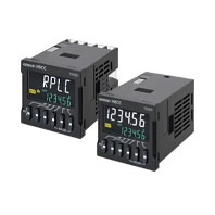
New and improved design for easier use, programming, maintenance and user feedback. The improved user interface is intuitive and offers better overall visibility. Replacement time notification function notifies the user of potential preventive maintenance.
Related Contents
- Features
- Lineup
- Specifications
- Dimensions
- Catalog / Manual / CAD / Software
last update: November 5, 2024
Ratings
| Item | Models | H5CC-A[] | H5CC-A11[] | H5CC-L8[] |
|---|---|---|---|---|
| Classification | Standard Type | Economy Type | ||
| Ratings | Power supply
voltage *1 |
• 100 to 240 VAC 50/60 Hz
• 12 to 48 VDC/24 VAC 50/60 Hz • 24 to 240 VDC/24 to 240 VAC 50/60 Hz (only for the H5CC-[]F) |
||
| Allowable voltage fluctuation range | 85% to 110% of rated supply voltage (90% to 110% at 12 to 48 VDC) | |||
| Power consumption | Approx.6.5 VA at 100 to 240 VAC
Approx.5.4 VA/3.2 W at 24 VAC/12 to 48 VDC Approx. 5.6 VA/2.7 W at 24 to 240 VAC/24 to 240 VDC *2 |
|||
| Mounting method | Flush mounting | Flush mounting, surface mounting, DIN track mounting | ||
| External connections | Screw terminals | 11-pin socket | 8-pin socket | |
| Degree of protection | Compliant with IEC IP66 for panel surface only and when Y92S-P6 Waterproof Packing is used Certified for UL Type 1 | |||
| Digits | 6 digits | |||
| Time ranges | 0.001 s to 999.999 s, 0.01 s to 9999.99 s, 0.1 s to 99999.9 s, 1 s to 999999 s, 1 s to 99 h 59 min 59 s, 0.1 m to 99999.9 min, 1 min to 999999 min, 1 min to 9999 h 59 min, 0.1 h to 99999.9 h, 1 h to 999999 h | |||
| Timer mode | Elapsed time (Up), remaining time (Down) (selectable) | |||
| Inputs | Input signals | Signal, Reset, Gate | Signal, Reset
(no inputs on the H5CC-L8E[]) |
|
| Input method | No-voltage (NPN) input/voltage (PNP) input (switchable)
(only no-voltage input is available for the H5CC-A11F) No-voltage input ON impedance: 1 kΩ max. (Leakage current: approx. 12 mA when 0 Ω) (Approx. 1 mA for the H5CC-A11F) ON residual voltage: 3 V max. (1 V max. for the H5CC-A11F) OFF impedance: 100 kΩ min. Voltage input High (logic) level: 4.5 to 30 VDC Low (logic) level: 0 to 2 VDC (Input resistance: approx. 4.7 kΩ) |
No-voltage input
On-impedance: 1 kΩ max. (Leakage current: 12 mA when 0 Ω) ON residual voltage: 3 V max. OFF impedance: 100 kΩ min. |
||
| Signal, reset, gate | Minimum input signal width: 1 or 20 ms (selectable, 50 ms for the H5CC-A11F) | |||
| Reset system | Power reset (depending on output mode),
external reset, manual reset, automatic reset (depending on output mode) |
|||
| Power reset | Minimum power-opening time: 0.5 s (except for A-3, b-1, F, ton-1, and toff-1 mode)
(1 s for the H5CC-AU[] and 0.1 s for the H5CC-[]F) |
|||
| Reset voltage | 10% max. of power supply voltage | |||
| Sensor waiting time | 250 ms max.
(Control output is turned OFF and no input is accepted during sensor waiting time.) |
|||
| Output | Output modes | A: Signal ON delay I, A-1: Signal ON delay II, A2: Power ON delay I, A3: Power ON delay II, b: Flicker I, b-1: Flicker II, b-5: One-shot flicker, C: Signal ON/OFF delay I, d: Signal OFF delay I, E: Interval, F: Cumulative, G: Signal ON/OFF delay II, H: Signal OFF delay II, Z: ON/OFF-duty-adjustable flicker, S: Stopwatch, toff: Flicker
OFF start I, ton: Flicker ON start I, toff-1: Flicker OFF start II, ton-1: Flicker ON start II |
||
| H5CC-L8E[]
A2: Power ON delay I, b: Flicker I, E: Interval, Z: ON/OFF-duty-adjustable flicker, toff: Flicker OFF start I, ton: Flicker ON start I |
||||
| One-shot time | 0.01 to 99.99 s | |||
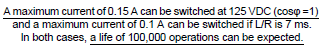
| Control output | • Models with Contact Outputs
5 A at 250 VAC/30 VDC, resistive load (cos =1) Minimum applicable load: 10 mA at 5 VDC (failure level: P, reference value) Contact materials: AgSnIn • Transistor output: NPN open collector, 100 mA at 30 VDC max., residual voltage: 1.5 VDC max. (Approx. 1 V), Leakage current: 0.1 mA max. |
|||
| External power supply | 12 VDC (±10%), 100 mA (only for the H5CC-AU[])
Note. Refer to Precautions for Correct Use on Data Sheet for details. |
|||
| Display method *3 | 7-segment, negative transmissive LCD;
Present value: 10-mm-high characters, white Set value: 6-mm-high characters, green |
7-segment, negative transmissive LCD;
Present value: 10-mm-high characters, white Set value: 6-mm-high characters, green |
||
| Memory backup | No-volatile memory (overwrites: 100,000 times min.) that can store data for 10 years min. | |||
| Operating temperature range | -10 to 55°C
(-10 to 50°C if timers are mounted side by side) (with no icing or condensation) |
|||
| Storage temperature range | -25 to 70°C (with no icing or condensation) | |||
| Operating humidity range | 25% to 85% | |||
| Case color | Black (N1.5) | |||
| Attachments | Flush mounting adapter,
waterproof packing, terminal cover |
―― | ||
*1. Do not use the output from an inverter as the power supply. The ripple must be 20% maximum for DC power.
*2. Inrush current will flow for a short time when the power supply is turned ON.
Inrush Current (Reference Values)
| Voltage | Applied voltage | Inrush current (peak value) | Time |
|---|---|---|---|
| 100 to 240 VAC | 264 VAC | 6.5 A | 0.74 ms |
| 12 to 48 VDC/24 VAC | 26.4 VAC | 13.6 A | 0.88 ms |
| 52.8 VDC | 12.9 A | 0.80 ms | |
| 24 to 240 VDC/24 to 240 VAC | 264 VAC | 5.5 A | 0.26 ms |
| 264 VDC | 3.9 A | 0.26 ms |
*3. The display is lit only when the power is ON. Nothing is displayed when power is OFF.
| Item | Models | H5CC-AWSD |
|---|---|---|
| Classification | Digital Timer with two-stage setting, and forecast output | |
| Ratings | Power supply voltage | 12 to 48 VDC/24 VAC 50/60 Hz |
| Allowable voltage fluctuation range | 85% to 110% of rated supply voltage (90% to 110% at 12 to 48 VDC) | |
| Power consumption | Approx. 5.32 VA/3.17 W at 24 VAC/12 to 48 VDC *1 | |
| Mounting method | Flush mounting | |
| External connections | Screw terminals | |
| Degree of protection | Compliant with IEC IP66 for panel surface only and when Y92S-P6 Waterproof Packing is used Certified for UL Type 1 | |
| Time range | 0.001 s to 999.999 s, 0.01 s to 9999.99 s, 0.1 s to 99999.9 s, 1 s to 999999 s, 1 s to 99 h 59 min 59 s, 0.1 min to 99999.9 min, 1 min to 999999 min, 1 min to 9999 h 59 min, 0.1 h to 99999.9h, 1 h to 999999 h | |
| Timer mode | Elapsed time (Up) | |
| Inputs | Input signals | Signal, reset, gate |
| Input method | No-voltage (NPN) input/voltage (PNP) input (switchable)
No-voltage input ON impedance: 1 kΩ max. (Leakage current: 12 mA when 0 Ω) ON residual voltage: 3 V max. OFF impedance: 100 kΩ min. Voltage input High (logic) level: 4.5 to 30 VDC Low (logic) level: 0 to 2 VDC (Input resistance: approx. 4.7 kΩ) |
|
| Signal, reset, gate | Minimum input signal width: 1 or 20 ms (selectable, same for all input) | |
| Reset system | Power resets (only for A mode), external and manual reset | |
| Power reset | Minimum power-opening time: 0.5 s (except for F-1 mode) | |
| Reset voltage | 10% max. of power supply voltage | |
| Sensor waiting time | 250 ms max.
(Control output is turned OFF and no input is accepted during sensor waiting time.) |
|
| Outputs | Output modes | A, F-1 |
| Output type | Transistor output: NPN open collector,
100 mA at 30 VDC max. residual voltage: 1.5 VDC max. (Approx. 1 V) Leakage current: 0.1 mA max. |
|
| Display | 7-segment, negative transmissive LCD;
Present value: 10-mm-high characters, white Set value: 6-mm-high characters, green *2 |
|
| Memory backup | No-volatile memory (overwrites: 100,000 times min.)
that can store data for 10 years min. |
|
| Operating temperature range | -10 to 55°C (-10 to 50°C if timers are mounted side by side)
(with no icing or condensation) |
|
| Storage temperature range | -25 to 70°C (with no icing or condensation) | |
| Operating humidity range | 25% to 85% | |
| Case color | Black (N1.5) | |
| Attachments | Waterproof packing, flush mounting adapter, terminal cover | |
*1.Inrush current will flow for a short time when the power supply is turned ON.
Inrush Current (Reference Values)
| Voltage | Applied voltage | Inrush current (peak value) | Time |
|---|---|---|---|
| 12 to 48 VDC/24 VAC | 52.8 VAC | 13.6 A | 0.88 ms |
| 42.8 VDC | 12.9 A | 0.80 ms |
*2.The display is lit only when the power is ON. Nothing is displayed when power is OFF.
Characteristics
| Accuracy of operating time and setting error
(including temperature and voltage influences) |
Power-ON start: ±0.01%±0.05 s max. *1
Signal start: ±0.005%±0.03 s max. *1 Signal start for transistor output model: ±0.005%±3 ms max. *1 *2 If the set value is within the sensor waiting time at startup the control output of the H5CC will not turn ON until the sensor waiting time passes. *1.The values are based on the set value. *2.The value is applied for a minimum input signal width of 1 ms. |
|
|---|---|---|
| Insulation resistance | 100 MΩ min. (at 500 VDC)
between current-carrying terminal and exposed non-current-carrying metal parts, between non-continuous contacts |
|
| Dielectric strength | 2,900 VAC, 50/60 Hz for 1 min between current-carrying terminal and operating section
2,000 VAC, 50/60 Hz for 1 min between power supply and input circuits for models other than the H5CC-A11F and H5CC-L8E[] (1,500 VAC for 12 to 48 VDC/24 VAC) 1,500 VAC, 50/60 Hz for 1 min between control output, power supply, and input circuits (for models other than the H5CC-L8E[]) for H5CC-[]SD 2,000 VAC, 50/60 Hz for 1 min between control output, power supply, and input circuits (for models other than the H5CC-L8E[]) for other models 1,000 VAC, 50/60 Hz for 1 min between non-continuous contacts |
|
| Impulse withstand voltage | 5 kV (between power terminals) for 100 to 240 VAC, 1.0 kV for 24 VAC/12 to 48 VDC
7.4 kV (between current-carrying terminal and operating section) |
|
| Static immunity | Malfunction: 8 kV
Destruction: 15 kV |
|
| Vibration resistance | Destruction | 10 to 55 Hz with 0.75-mm single amplitude each in three directions for 2 h each |
| Malfunction | 10 to 55 Hz with 0.35-mm single amplitude each in three directions for 10 min each | |
| Shock resistance | Destruction | 300 m/s2 in three directions, three cycles |
| Malfunction | 100 m/s2 in three directions, three cycles | |
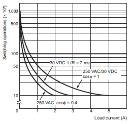
| Life expectancy | Mechanical | 10,000,000 operations min.
(under no load at switching frequency of 1,800 operations/h and ambient temperature of 23°C) |
| Electrical | 100,000 operations min.
(5 A at 250 VAC, resistive load at 1,800 operations/h and ambient temperature of 23°C) * |
|
| Weight | Approx. 115 g (Timer only) | |
*Refer to Electrical Life Test Curve.
Electrical Life Test Curve (Reference Values)
Applicable Standards
| Approved safety standards | cULus (or cURus): UL508/CSA C22.2 No. 14 *1
Conforms to EN61812-1: Pollution degree 2/overvoltage category III B300 PILOT DUTY, 1/4 HP 120 VAC, 1/3 HP, 240 VAC, 5 A, 250 VAC/30 VDC resistive load VDE0106/P100 CCC: GB/T 14048.5 Pollution degree 2/overvoltage category III *2 RCM UKCA |
|---|---|
| EMC | (EMI) EN61812-1
Emission Enclosure: EN55011 Group 1 class A Emission AC mains: EN55011 Group 1 class A (EMS) EN61812-1 Immunity ESD: EN61000-4-2: 4 kV contact discharge 8 kV air discharge Immunity RF-interference: EN61000-4-3: 10 V/m (Amplitude modulated, 80 MHz to 1 GHz); 3 V/m (Amplitude modulated, 1.4 G to 2 GHz); 1 V/m (Amplitude modulated, 2 G to 2.7 GHz); 10 V/m (Pulse-modulated, 900 MHz±5 MHz) Immunity Conducted Disturbance: EN61000-4-6: 10 V (0.15 to 80 MHz) Immunity Burst: EN61000-4-4: 2 kV power-line; 1 kV I/O signal-line Immunity Surge: EN61000-4-5: 1 kV line to lines (power and output lines (relay outputs)); 2 kV line to ground (power and output lines (relay outputs)) Immunity Voltage Dip/Interruption: EN61000-4-11: Voltage Dip 1 cycle, 100% (rated voltage) 10/12 cycle, 60% (rated voltage) 25/30 cycle, 30% (rated voltage) Interruption 250/300 cycle, 100% (rated voltage) |
*1.The following safety standards apply to models with sockets (H5CC-L8[]/-A11[]).
cUL (Listing): Applicable when an OMRON P2CF(-E) Socket is used.
cUR (Recognition): Applicable when any other socket is used.
*2.CCC certification requirements
| Rated operating voltage Ue
Rated operating current Ie |
Contact output:
AC-15: Ue: 250 VAC, Ie: 3 A AC-13: Ue: 250 VAC, Ie: 5 A DC-13: Ue: 30 VDC, Ie: 0.5 A Transistor output: DC-13: Ue: 30 VDC, Ie: 0.1 A |
|---|---|
| Rated insulation voltage | 250 V |
| Rated impulse withstand voltage
(altitude: 2,000 m max.) |
4 kV (at 240 VAC) |
| Conditional short-circuit current | 1000 A |
I/O Functions
For details, refer to the timing charts on Data Sheet.
| Inputs *1 | Start signal | Normally functions to start timing.
In modes A-2 and A-3, disable timing. In mode S, starts and stops timing. |
|
|---|---|---|---|
| Reset | •Resets present value. (In elapsed time mode, the present value returns to 0; in remaining time mode, the present value returns to the set value.)
•Count inputs are not accepted and control output turns OFF while reset input is ON. •Reset indicator is lit while reset input is ON. |
||
| Gate *2 | Disables timing. (If a reset occurs while the gate input is ON, a reset will be performed.) | ||
| Outputs | Control output (OUT) | Outputs take place according to designated operating mode when timer reaches corresponding set value. | |
| Forecast value setting *3 | Control output (OUT2) | Turns ON when the present value reaches the set value. | |
| Forecast output (OUT1) | Turns ON when the present value reaches the forecast value. | ||
| Absolute value setting *3 | Control output 2 (OUT2) | Turns ON when the present value reaches the set value 2. | |
| Control output 1 (OUT1) | Turns ON when the present value reaches the set value 1. | ||
*1.The H5CC-L8E[] does not have an input.
*2.The H5CC-L[] does not have a gate input.
*3.For the H5CC-AWSD.
Response Delay Time When Resetting (Transistor Output)
The following table shows the output delay time from when the reset signal is input until the output is turned OFF.
(Reference value)
| Minimum reset signal width | Output delay time |
|---|---|
| 1 ms | 0.58 to 0.78 ms |
| 20 ms | 13.7 to 17.2 ms |
last update: November 5, 2024